8. Connect Cables
During this step you will be connecting the motor and limit switch cables to the machine and then to the controller.
Video
Tools
- 2mm allen key
- 2.5mm allen key
- 3mm allen key
Hardware
- M3x6 flat head screw x 17
Cables
- Y1 motor cable
- Y2 motor cable
- Y1 limit switch cable
- Y2 limit switch cable
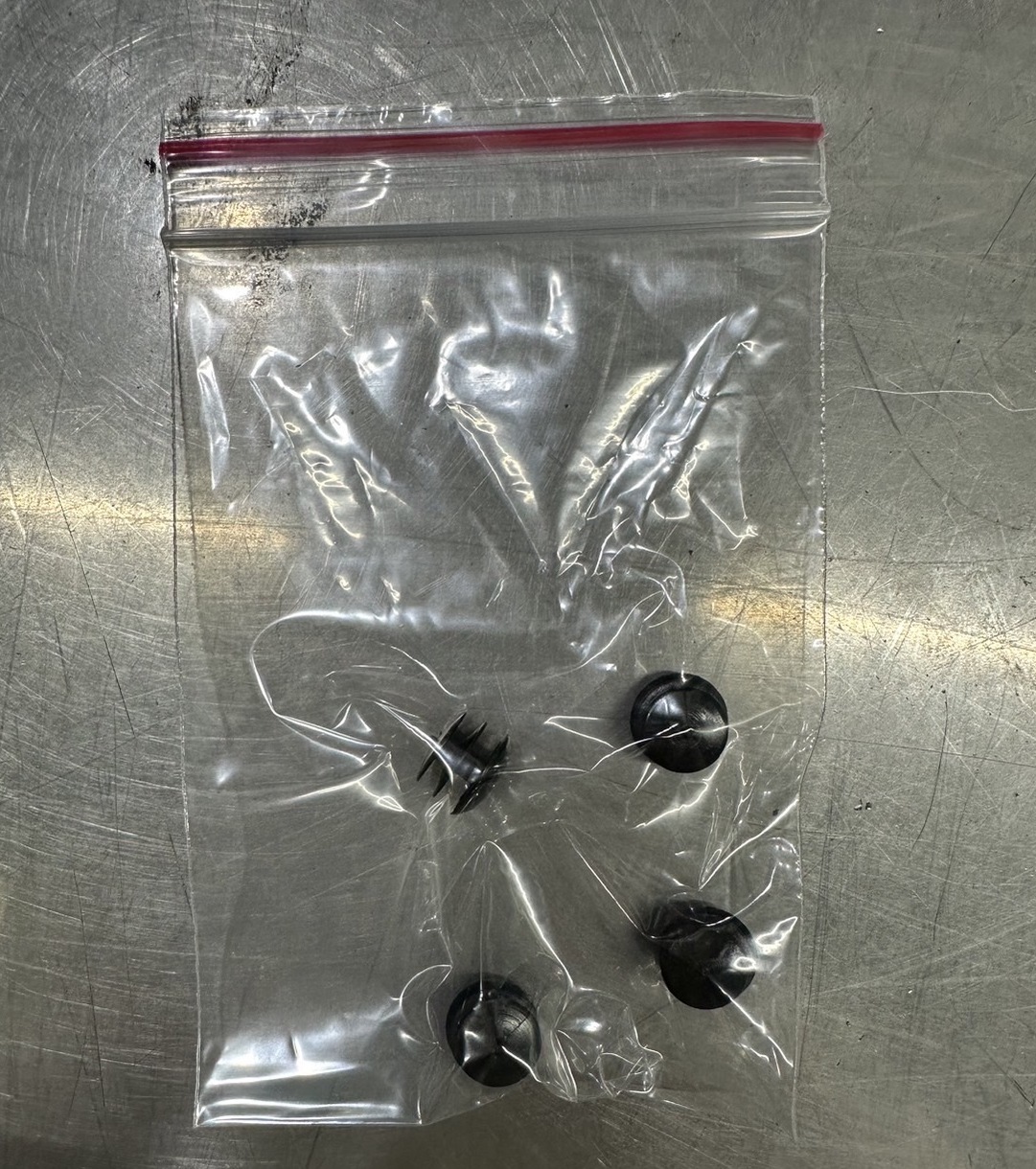
Note: 2 extra homing switches have been provided in case of failure. All homing switches required for the machine to function properly come pre-installed on the machine.
Steps
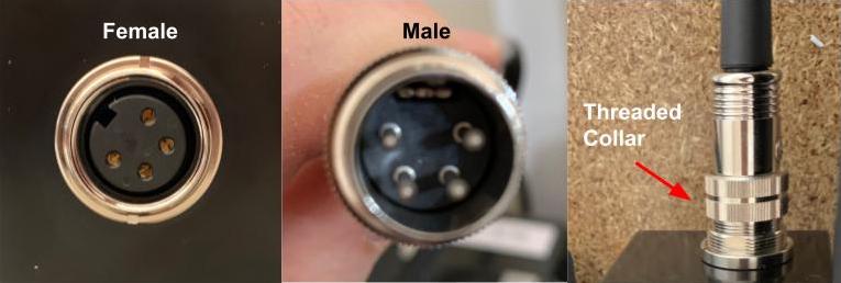
- Identify Motor and Limit Switch Cables
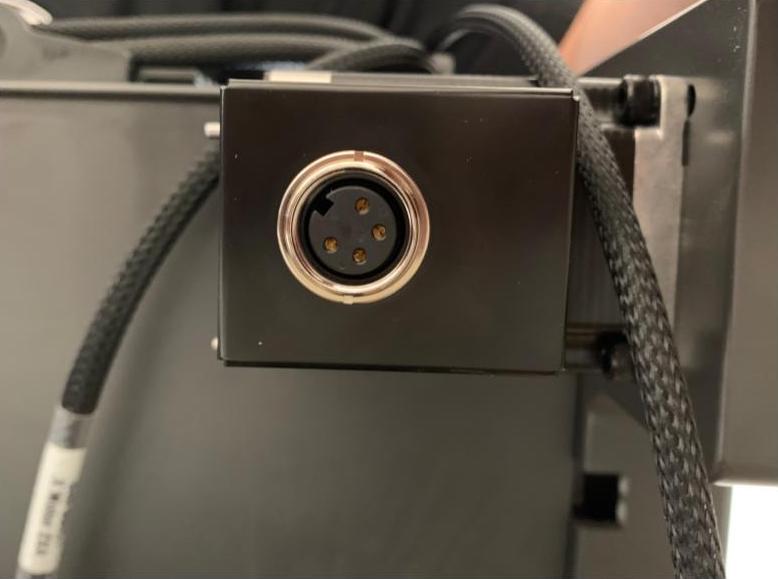
- The motor cable connectors will only connect in a single orientation. The motor connectors include a feature that allows the connectors to securely attach together by threading a metal collar from the male end into the female end.
- The motor cable connectors will only connect in a single orientation. The motor connectors include a feature that allows the connectors to securely attach together by threading a metal collar from the male end into the female end.
- Connect Motor Cables and Limit Switches to Z-Axis
- Insert the Z-axis motor cable into the female connector and thread the collar onto the connector.
- Connect the Z-axis limit switch from the drag chain to the black/blue limit switch pigtail at the front of the Z-axis.
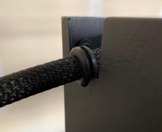
- Route the spindle cable through the notch on the left hand side of the Z-axis. Slide the gasket installed on the spindle cable into the notch.
- Once the spindle cable has been connected to the spindle, place the Z-axis cover back on top of the Z axis and secure it using a 2.5mm allen key and the 6 M3x10mm screws from step 7.
- Place the included plastic plugs into the 4 holes where the screws were tightened. The plugs will ensure that no dust or debris will gather on top of the screws and allow for easier removal of the Z axis cover if needed for maintenance.
- Insert the Z-axis motor cable into the female connector and thread the collar onto the connector.
- Connect Motor Cables and Limit Switches to X Axis
- Insert the X-axis motor cable into the female connector behind the gantry and thread the collar into the connector.
NOTE: If you purchased a CSA unit (Canadian customers), the motor covers will look different.
- Insert the X-axis motor cable into the female connector behind the gantry and thread the collar into the connector.
CSA stepper motor cover, click for details
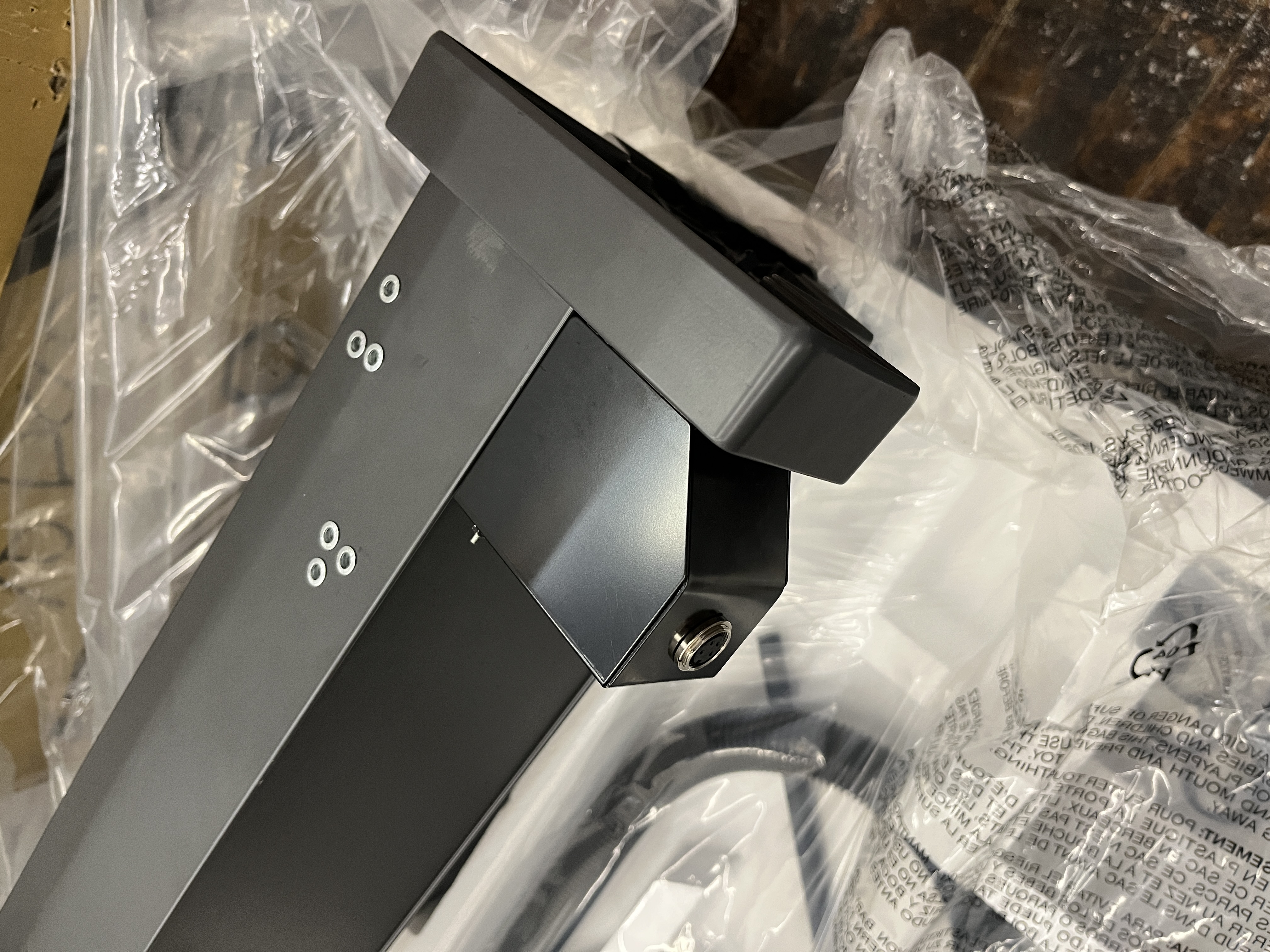
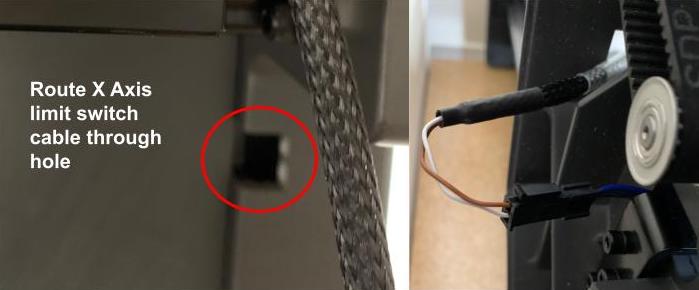
- Route the X-axis limit switch through the hole in the back of the Y1 gantry riser and attach to the black/blue limit switch pigtail on the X-axis. Attach a zip tie through the white zip tie pad to keep the connector in place.
- Attach X Axis Riser Covers
- Use a 2mm allen key and 9x M3x6 flat head screws to attach the Y1 metal riser cover to the Y1 side of the gantry. The riser covers are located under the drag chain in the top section of the packaging.
- Repeat for the Y2 metal riser cover with 8x M3x6 flat head screws.
NOTE: Do not over-tighten the M3x6 flat head screws as doing so may lead to the strip the screws.
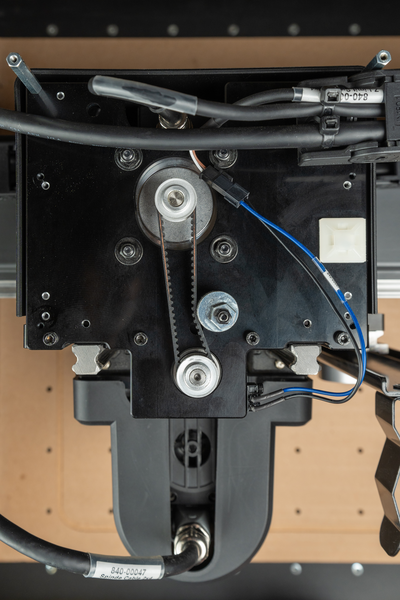
- Connect Motor Cables to Y1 and Y2 Axes
- Insert the Y1 axis motor cable (packaged separately) into the female connector on the Y1 motor and thread the collar into the connector.
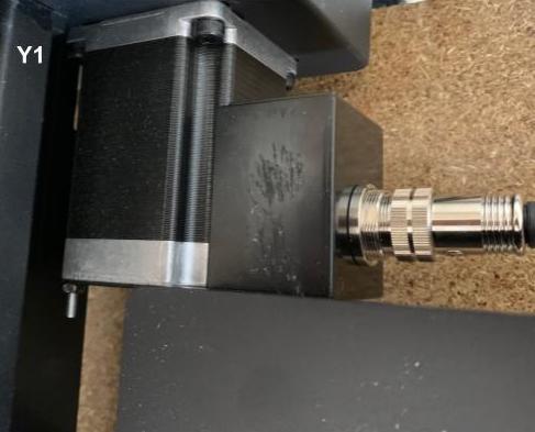
- Insert the Y2 axis motor cable (packaged separately) into the female connector on the Y2 motor and thread the collar into the connector.
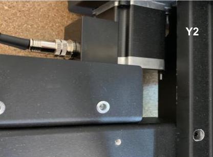
- Insert the Y1 axis motor cable (packaged separately) into the female connector on the Y1 motor and thread the collar into the connector.
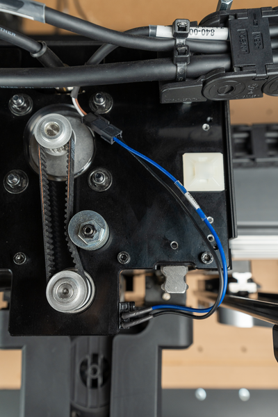
- Connect Limit Switch Cables to Y1 and Y2 Axes
- Attach the Y1 limit switch cable (packaged separately) to the black/blue pigtail coming out of the back of the Y1 front plate.
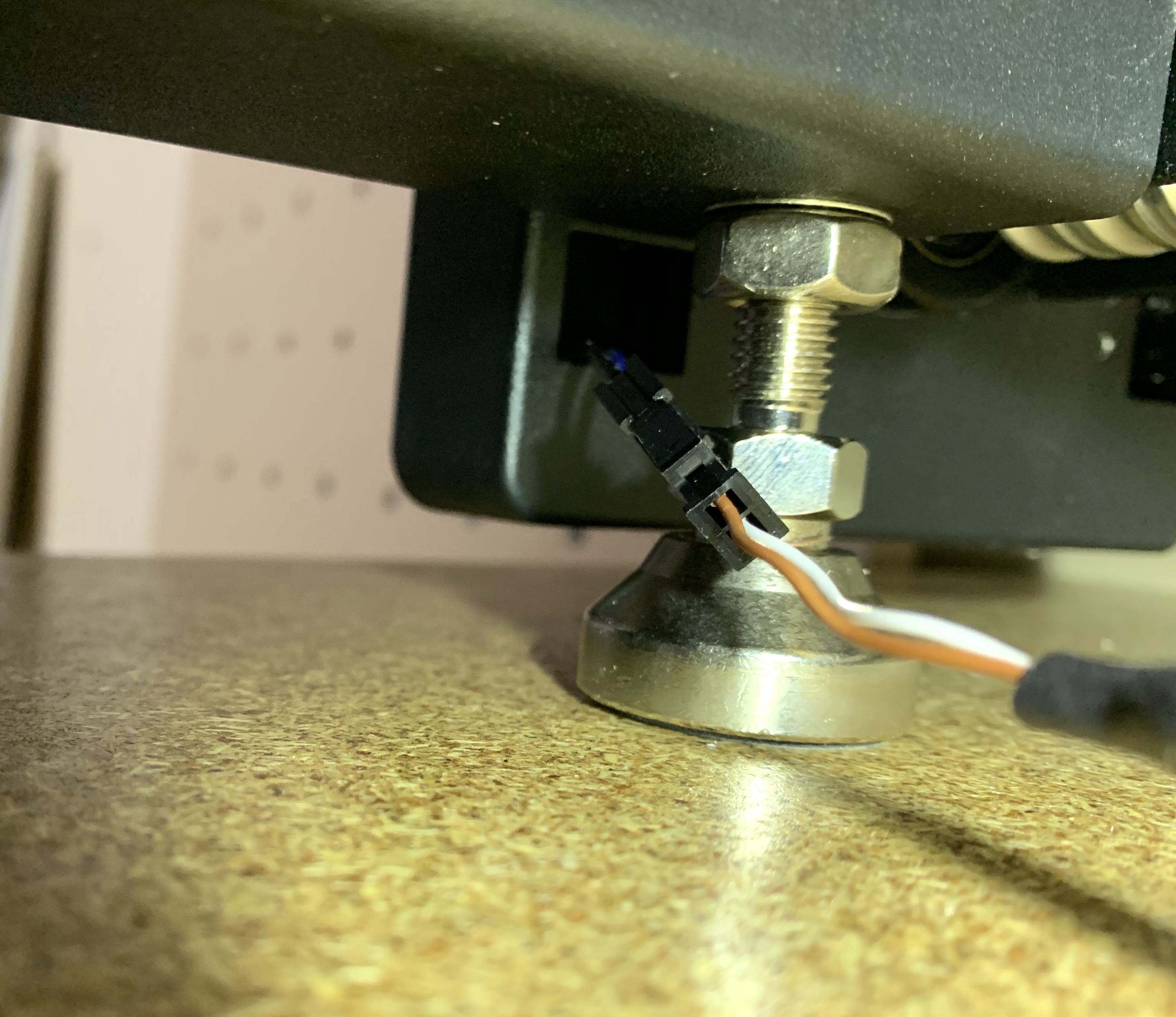
- Attach the Y2 limit switch cable (packaged separately) to the black/blue pigtail coming out of the back of the Y2 front plate.
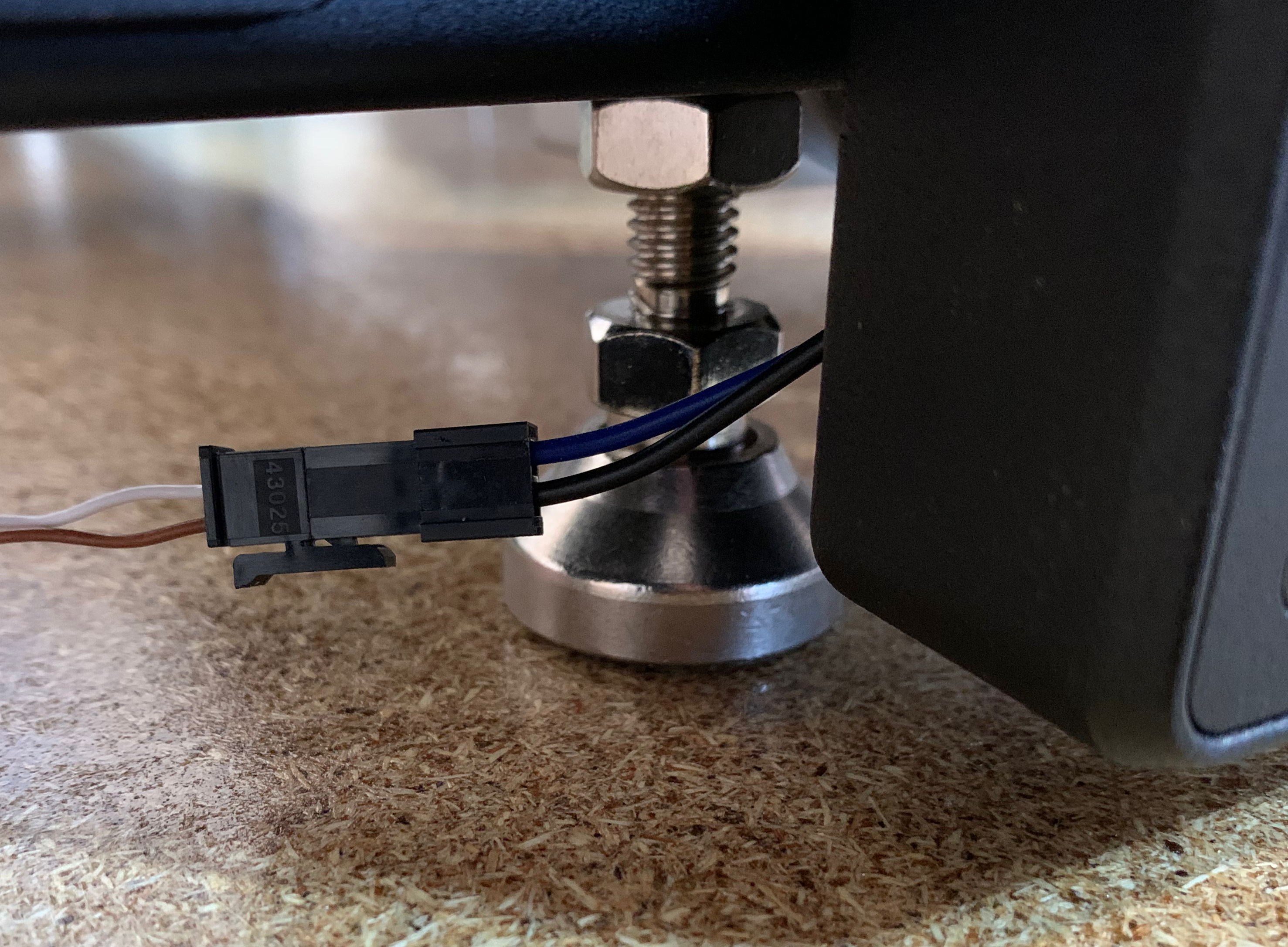
Note: Pigtail connector should be outside of the housing and secured under the crossmembers with a ziptie. Ensure cable is not getting pinched or touches the ballscrews.
- Attach the Y1 limit switch cable (packaged separately) to the black/blue pigtail coming out of the back of the Y1 front plate.
- Route Cables
- Route all of the cable ends that were inserted in step 10 under the machine frame and toward the back of the machine near where the controller is placed.