7. Install Drag Chains
During this step you will be affixing the prepared drag chain with installed cables to the X and Y-axes.
Video
Tools
- 3mm allen key
Hardware
- M5x16 BHCS x 8
- Flat washer x 8
Cable
Drag chain plate (metal)
Steps
- Identify Drag Chain Positioning
- The drag chain consists of a bundle of cables with 2 separate linked chains. Each linked chain will lay across an axis.
- Cut the zip ties holding the cables at the ends of each drag chain. This will allow you to access the mounting holes in the drag chains.
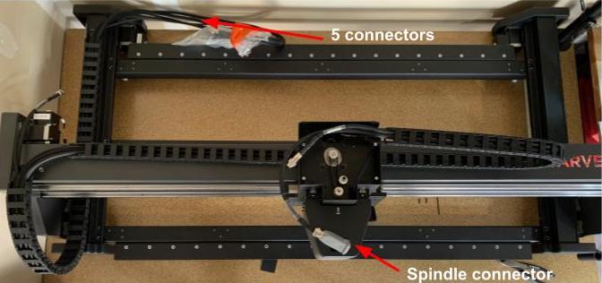
- The end of the X-axis drag chain includes 3 connectors: 1 for the spindle, 1 for the Z-axis motor, and 1 for the Z-axis limit switch.
- The end of the Y1 axis drag chain includes all cables that will terminate at the rear of the machine for connection to the controller. The Y-axis drag chain is wider than the X-axis drag chain
- Lay Out Drag Chains
- Lay the X-axis drag chain along the X-axis, looping it up to terminate at the top of the Z-axis.
- Lay the Y-axis drag chain across the top of the Y1 assembly, ensuring it loops across the front of the gantry and rests on top of the Y1 axis.
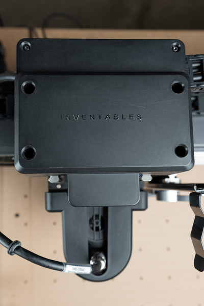
- Remove The Z-axis Cover
- Using a 2.5mm allen key, remove the 6 M3X10mm socket headcap screws from the top of the Z-axis cover. Lift off the Z axis cover and set aside.
- Using a 2.5mm allen key, remove the 6 M3X10mm socket headcap screws from the top of the Z-axis cover. Lift off the Z axis cover and set aside.
- Attach X Axis Drag Chain to Z-Axis
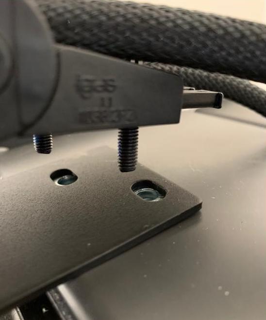
- Add a flat washer to each of 2x M5x16 screws and place through the holes at the last drag chain link. Tighten screws using a 3mm allen key.
- Add a flat washer to each of 2x M5x16 screws and place through the holes at the last drag chain link. Tighten screws using a 3mm allen key.
- Attach X Axis Drag Chain to X Axis
- Add a flat washer to each of 2x M5x16 screws and place through the holes at the last drag chain link. Tighten screws to the top of the X-axis extrusion using a 3mm allen key.
- Attach Y-Axis Drag Chain to X Axis
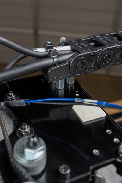
- Add a flat washer to each of 2x M5x16 screws and place through the holes at the last drag chain link. Place the drag chain plate between the drag chain and gantry and tighten screws using a 3mm allen key. The drag chain plate will ensure that the cables maintain their proper bend radius throughout machine motion, extending the life of the cables.
- Add a flat washer to each of 2x M5x16 screws and place through the holes at the last drag chain link. Place the drag chain plate between the drag chain and gantry and tighten screws using a 3mm allen key. The drag chain plate will ensure that the cables maintain their proper bend radius throughout machine motion, extending the life of the cables.
- Attach Y-Axis Drag Chain to Y-Axis
- Add a flat washer to each of 2x M5x16 screws and place through the holes at the last drag chain link at the rear end of the Y1 axis. Tighten screws using a 3mm allen key.
- Reinstall zip ties at the end of each drag chain so the cables are directly attached to the drag chain.