4. Assemble Frame
During this step you will be assembling the base frame of the X-Carve Pro, leveling, and squaring it to prepare for the installation of the gantry.
Video
Tools
- 4mm allen key
- Torque wrench w/ 4mm hex bit
- 17mm open end wrench x 2
- Square
Hardware
- Socket Head Cap Screw (SHCS) M5x16 w/ spring washer x 24
Steps
- Set Torque Wrench to 4.5N*M
- The torque wrench included with the X-Carve Pro toolkit has a settable range of 1.0 to 5.0 NM. For the X-Carve Pro, all screws requiring a proper torque setting will need to be set to 4.5 NM.
- To set your torque wrench to 4.5 N*M, pull the silver handle down and turn the head of the torque wrench clockwise until the 0 on the black collar lines up with 4.5 on the shaft. Once the 0 and 4.5 are aligned, slide the silver collar up to click into place.
- Install the 4mm hex socket onto your torque wrench.
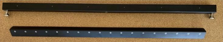
- Install Clamp Extensions
- Install clamp extensions on the crossmembers with leveling feet. Use 6 SHCS M5x16 w/ spring washer and 4mm allen key. The clamp bar should be oriented so the top of the clamp bar is level with the top of the crossmember.
 Once the screws have been installed, use the torque wrench to tighten each screw to 4.5 N*M.
Repeat this process for the rear crossmember.
- Install clamp extensions on the crossmembers with leveling feet. Use 6 SHCS M5x16 w/ spring washer and 4mm allen key. The clamp bar should be oriented so the top of the clamp bar is level with the top of the crossmember.
- Adjust Leveling Feet
- Screw the leveling feet into the crossmembers clockwise by hand so the set screws are flush with the bottom of the crossmember. This will make it easier to attach the crossmembers to the Y-axes and level the machine.
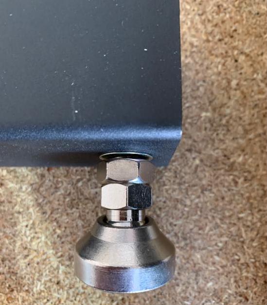
- Screw the leveling feet into the crossmembers clockwise by hand so the set screws are flush with the bottom of the crossmember. This will make it easier to attach the crossmembers to the Y-axes and level the machine.
- Attach Crossmembers to Y1 Axis
- Working from the front of the machine toward the rear, attach each crossmember to the Y1 axis using 2x M5x16 SHCS w/ Spring Washer and a 4mm allen key. Be sure not to over-tighten the crossmembers to the Y1-axis at this time—you will be tightening with the torque wrench in a later step. Crossmembers should be finger-tight to the Y1 axis.
NOTE: For cross members 2 and 4 without leveling feet, loosely thread the screws on until they are attached to the Y2 axis in a later step.
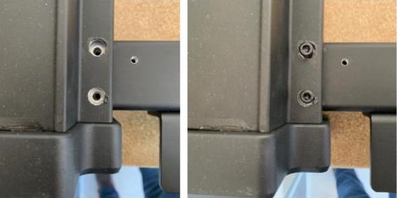
- Repeat with the other crossmembers until they all are connected and tight to the Y1 axis.
- Working from the front of the machine toward the rear, attach each crossmember to the Y1 axis using 2x M5x16 SHCS w/ Spring Washer and a 4mm allen key. Be sure not to over-tighten the crossmembers to the Y1-axis at this time—you will be tightening with the torque wrench in a later step. Crossmembers should be finger-tight to the Y1 axis.
- Attach Crossmembers to Y2 Axis
- Line up each of the crossmembers so they are in line with the Y2 axis holes. Attach each of the remaining crossmembers with 2xM5x16 SHCS w/ Spring Washers to the Y2 axis using the 4mm allen key. Do not over-tighten at this point, only turn to finger-tight.
- Line up each of the crossmembers so they are in line with the Y2 axis holes. Attach each of the remaining crossmembers with 2xM5x16 SHCS w/ Spring Washers to the Y2 axis using the 4mm allen key. Do not over-tighten at this point, only turn to finger-tight.
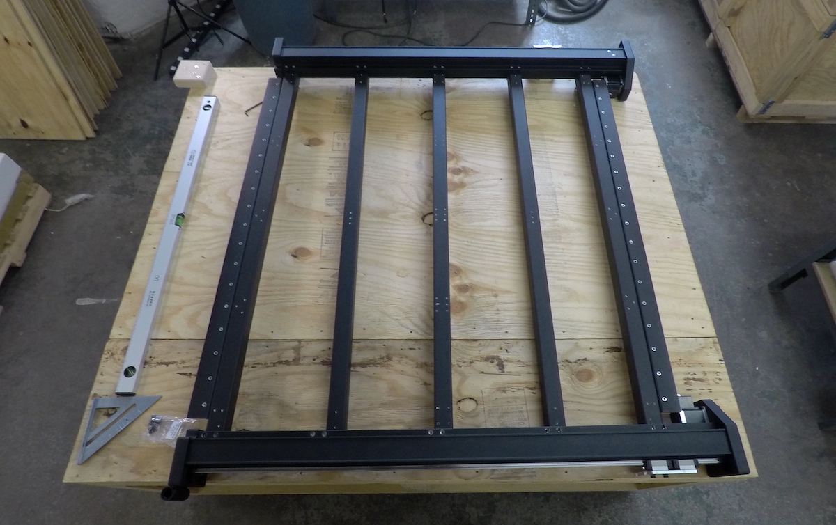
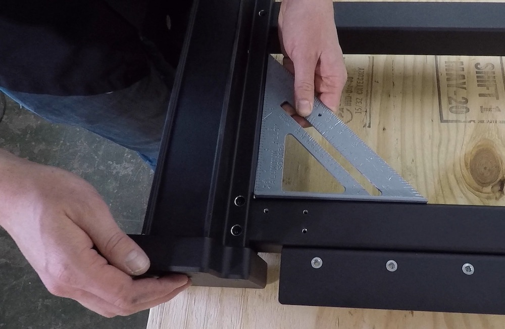
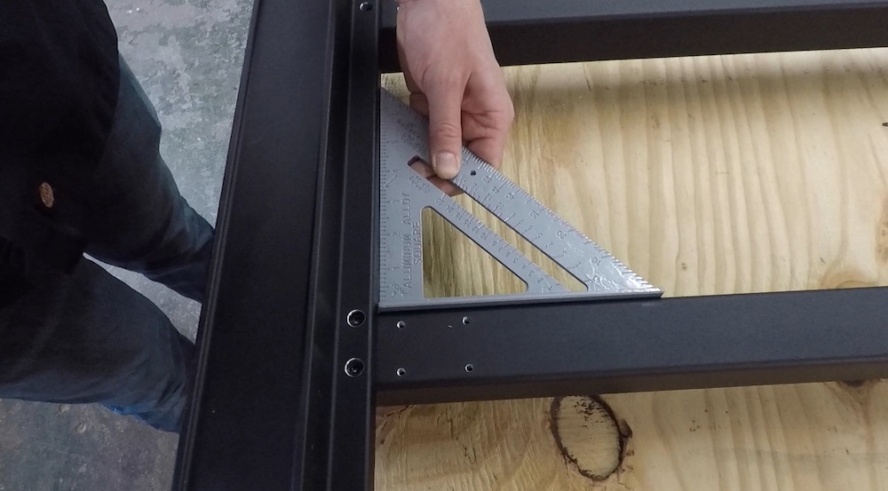
- Square the Crossmembers to Y1
-
Place the rafter square between the Y1 axis and first crossmember. Slide the Y1 axis or crossmember until both components are flush with the edges of the square. Once the first crossmember is square to Y1, repeat with remaining crossmembers, working your way toward the rear of the machine.
-
Crossmember 3
-
Crossmember 5
-
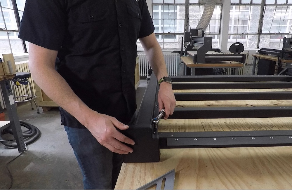
- Torque Crossmembers to Y1 Axis
- With the 4mm hex socket installed on your torque wrench, tighten all of the screws inserted through the Y1 axis into the crossmembers to 4.5 N*M. Work your way from the front of the machine toward the rear, ensuring that you tighten until the torque wrench ‘clicks’ and head pivots.
Do not tighten the Y2 axis crossmembers with the torque wrench at this time. Torquing the screws on the Y2 axis will be completed during the machine squaring procedure in step 13.